 |
 |
 |
|
"KSU" board Plugs directly into the KSU, and RJ45 cables run out to the phones. |
"PHONE" board These are for the "phone end" of the RJ45 cables. Phones plug directly into this board. | |
These two cards can be used together to replace long runs of 25 pair cable in 1A2 phone systems between the KSU and phone extensions using runs of a few cat5 network cables.
See Revisions for more info on the different versions of this board.
Here's the pair of finished printed boards:
|
|
|
|
"KSU" board Plugs directly into the KSU, and RJ45 cables run out to the phones. |
"PHONE" board These are for the "phone end" of the RJ45 cables. Phones plug directly into this board. | |
On the left, a "Key System" board which handles the KSU end of the connection.
On the right, a "Phone" board which handles the phone extension end of the connection, which can optionally be multipled (bridged) to chain several extensions.
Potentially long RJ45 network cables connect the boards together (can be cat5, cat5e, etc). Each cable can carry 4 pairs of 1A2 signals. Up to three cables can be carry a total of 12 pairs.
Small 1A2 systems don't come close to using all 25 pairs of the fat telco cables, so network cables with fewer conductors can be used to carry just the minimum required signals. These boards are designed to provide the common needs of a small 1A2 system; up to 3 CO lines and Intercom (Lines #1, #2, #3, and #5):

Anywhere from one to three cables can be used, depending on how many 1A2 signals are needed, to minimize the amount cabling:
| RJ45 Port | Provides | Details |
|---|---|---|
| A | Line #1 + Ringer | An RJ45 cable for port "A" provides
Line #1 and the ringer (bell). Line #1 T/R/A/L and Bell (Y-S pair), and two conductors for ground: total of 8 conductors. |
| B | Line #2 + Line #3 | An RJ45 cable for port "B" provides
Lines #2 and #3 Line #2 and Line #3 T/R/A/L |
| C | Line #5 (ICM) + Buzzer | An RJ45 cable for port "C" provides
Line #5 (usually the Intercom) and buzzer. Line #5 T/R/A/L and buzzer (Y-O pair) |
You can provide these cables in any combinations shown below. Just be sure e.g. Cable "A" goes to the "A" connector at both ends; don't mix them up!
If you need more than what all 3 cables can
provide, you might as well use a 25 pair cable,
because more than 3 cat5 cables is about as thick as a 25 pair cable.
If you need any other kind of wiring, use 66
blocks with amphenol on the left and RJ45 connectors on the right,
so you can punch down any kind of RJ45 wiring you want.
So depending on what one needs, here are the common uses these boards were designed for:
 |
 |
 |
|
These boards also allow you to bridge multiple
phone extensions, e.g.
| Single Phone | Bridged Phones |
|---|---|
 |
 |
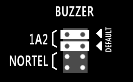
New in REV-D (and up), "BUZZER" jumpers allow handling the special wiring needs of the NT LOGIC 10 phones for connecting to a Seriss KSU. The default configuration of these jumpers is for standard "1A2" wiring, which passes the Y/O pair used for the buzzer straight through to the phone, as shown here:
But when NT LOGIC 10 sets are used, they need to have the Y/O buzzer pair from the KSU reassigned to the NT LOGIC 10 connector's spare pins 48 and 49. This pin reassignment must normally be handled with special wiring on a 66 block. But now these two "BUZZER" jumpers can handle this reassignment simply by moving the two jumpers from the default "1A2" setting over to the "NORTEL" setting, as shown here:
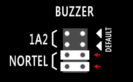
See the Seriss KSU manual for more info on the special wiring needed for NT LOGIC 10 set's buzzer to work correctly.
Here's the gerber
files which you can have printed very cost effectively (e.g. PCBway).
You can then populate the boards with the components using the Digikey
part numbers shown on the silk screen.
Here's the "Sprint Layout 6"
PCB .lay6 file which lets one redesign and re-generate gerber files.
Here's screenshots of what the board looks like inside Sprint 6 layout:
 Top and bottom copper + top silk |
 Top "Photo" View |
 Bottom "Photo" View |
Note that the recommended Digikey part numbers for the three RJ-45 sockets and the separate male and female Amphenol connectors appear on the silkscreen, printed below the connectors. (e.g. "A31407-ND" below the RJ-45's, etc).
For the "KEY SYSTEM" board's right-angle amphenol connector, a "solder type" connector is the only option.
For the "PHONE" board's amphenol, either a press-fit or a solder type can be used. (Avoid press-fit unless you have a press-fit jig)
The two boards are in a single layout, but will be cut into separate boards by the printer.
There are revision notes describing the features added in each revision.
There are separate websites for each revision of this board:
rev a,
rev b,
rev c,
rev d,
rev e.
The following animations show the changes between the current REV-E and previous REV-D:
all,
top,
bot,
photo-top,
photo-bot.