Logic Boards -- Suggested Logic I/O Layout for Printer#2 - 02/26/2010
-
This is my (Greg's) take on the logic wiring for the Home/Deenergize/Tension motors
using custom logic boards (green) mounted inside Printer#2 (behind front panel)
that will interface the computer parallel ports to the rest of the printer.
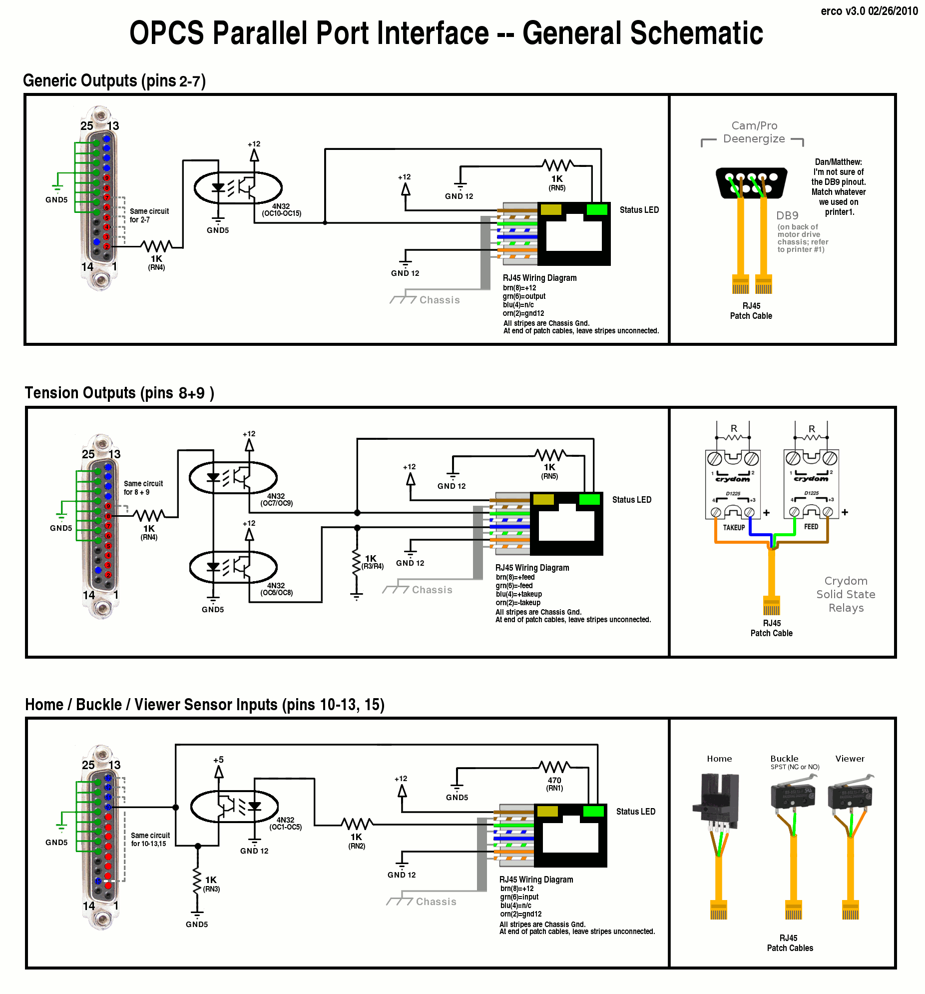
This schematic is what I used to actually layout the board in ExpressPCB,
which includes the ExpressPCB file, parts list, and my assembly instructions
for the Disney engineers to use to populate and solder up the boards themselves.
Using this new board should cleanup the wiring of Printer#2 so that we have a nice RJ-45 patch bay,
and straight parallel cables from computer to these boards, avoiding this kind of field wiring on the back
of Printer#1's DB-25. Instead, the parallel port cables would run straight from
the computer into the printer and plug directly into the interface boards.
Standard RJ45 CAT-V cables will be used from the boards out to the sensors/relays
on the printer.
Application Diagram
This diagram shows the problem to solve; print two circuit boards, one for each of the two parallel ports, to handle optically isolating and interfacing to the rest of the optical printer.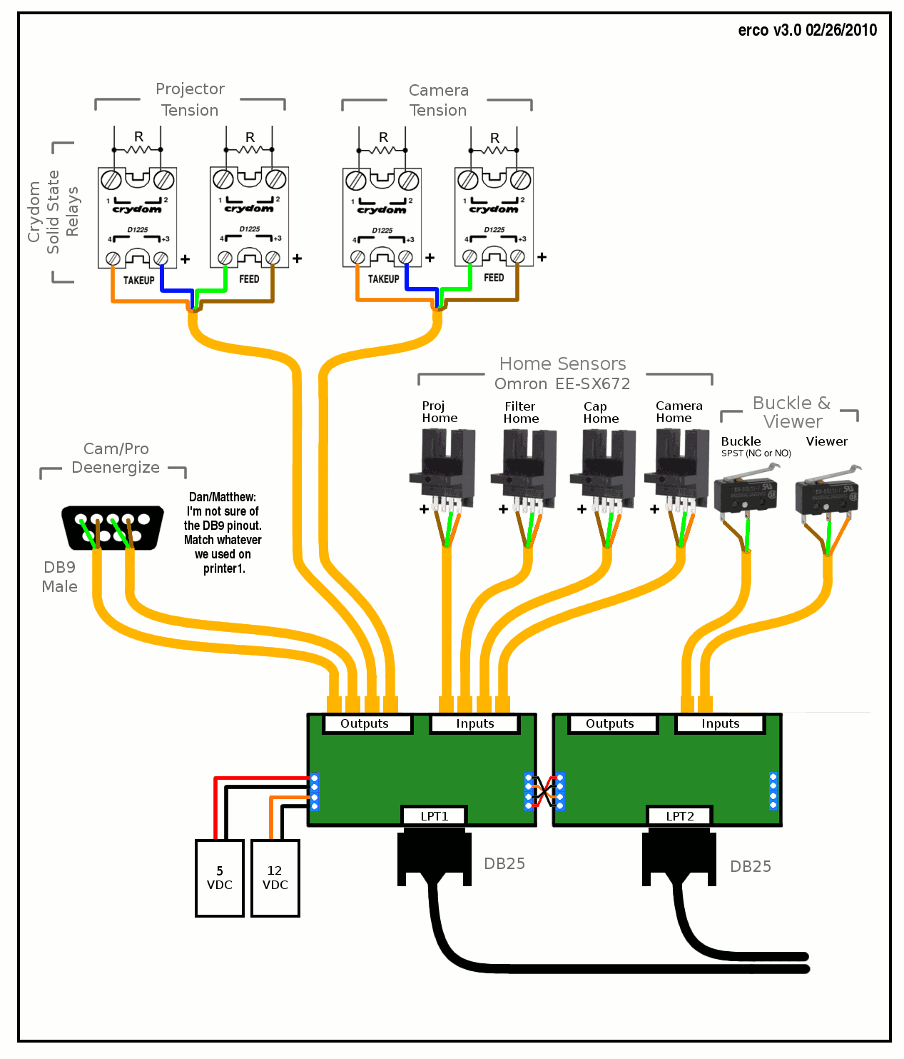
Logic + Schematic
Here's the Parallel Port interface board's proposed schematic and logic:
Printed Board
Here's the final printed Seriss logic board that handles the Parallel Port interfacing to the printer:

Installed Boards - 07/20/2010
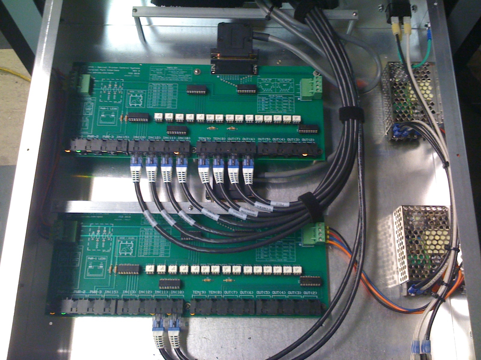
Here's the two logic boards installed in their final resting place in the printer.
Nice wiring job, guys! This pic taken in July 20 2010 on a final visit to see the
completed Printer#2 some time after it had been running for a while.
Printer#1 Photos 07/31/2009 -- Currently In Production
Captions along bottom of each image describe the photo.
First 12 images are of the printer we computerized a year or so ago (currently in production)
which I'm referring to as 'printer1'.
Below those are pictures of 'printer2', which is currently offline
and is the one we'll be working on computerizing next.
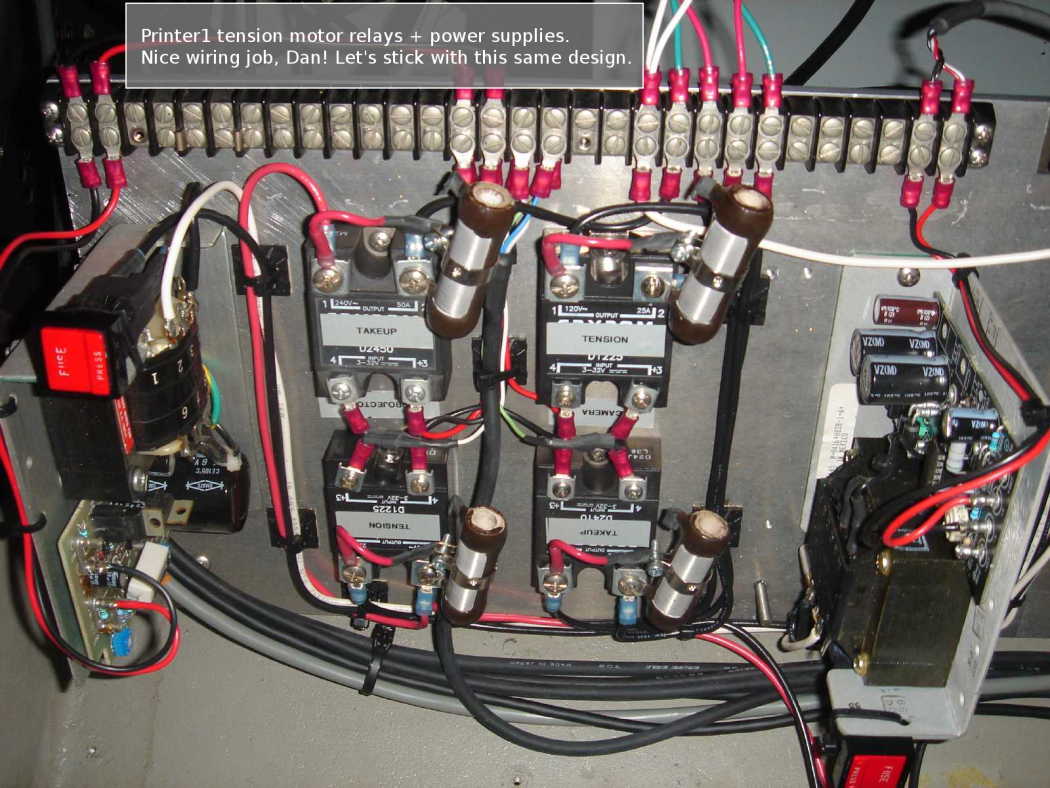
printer1-crydom-relays-leak-resistors-power-supplies.jpg
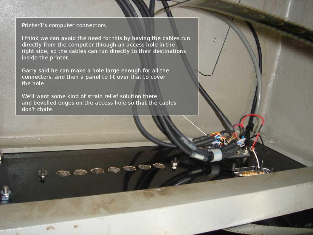
printer1-front-panel-computer-connections-rear.jpg
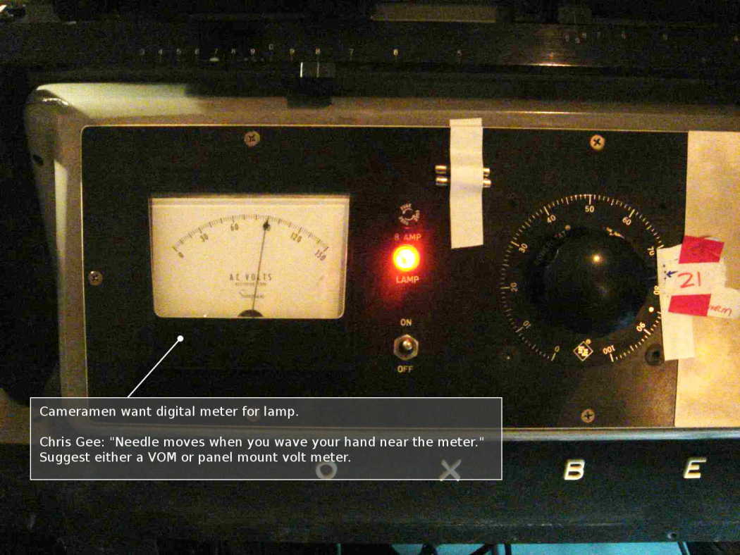
printer1-front-panel-lamp-meter-variac.jpg
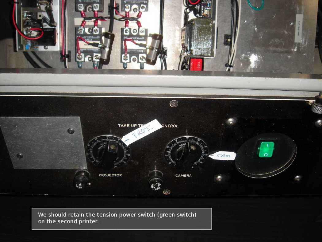
printer1-front-panel-tension-pro-cam-power.jpg
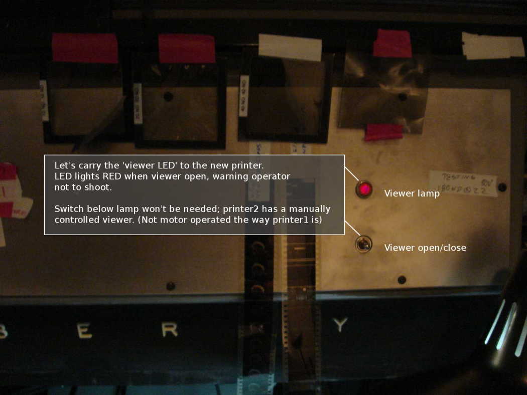
printer1-front-panel-viewer-lamp-and-switch.jpg
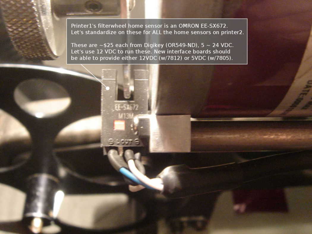
printer1-home-sensor-typical.jpg
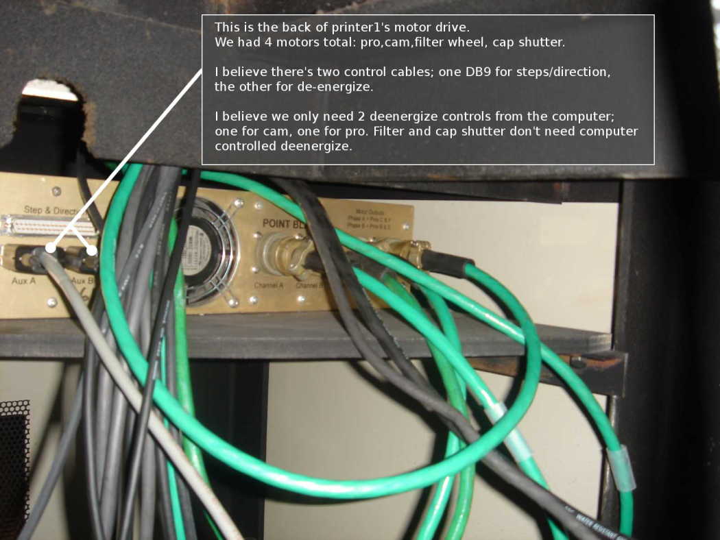
printer1-motor-drive-rear-and-shelf.jpg
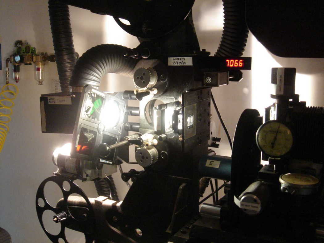
printer1-pro-head-filter-wheel.jpg
Shown: Y/C/M/X color wheel with color filter and ND filter holders.
Rotating cap shutter at right between projector gate and camera lens.
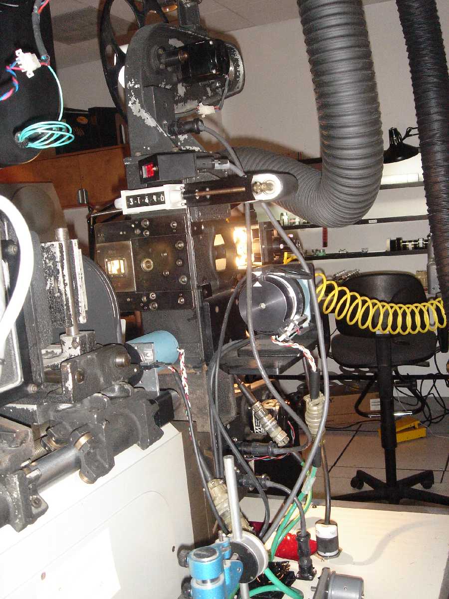
printer1-proj-head-rear.jpg
Shown: projector motor (right) and filter wheel motor (left).
Note alignment arrows (white triangles) on surfaces for visual
verification of proper home positions when the system is at rest.
Note green "military connectors" used to allow disconnect/removal
of motors. I'd advise using different connectors, as the screw locks
on these are hard to properly verify.
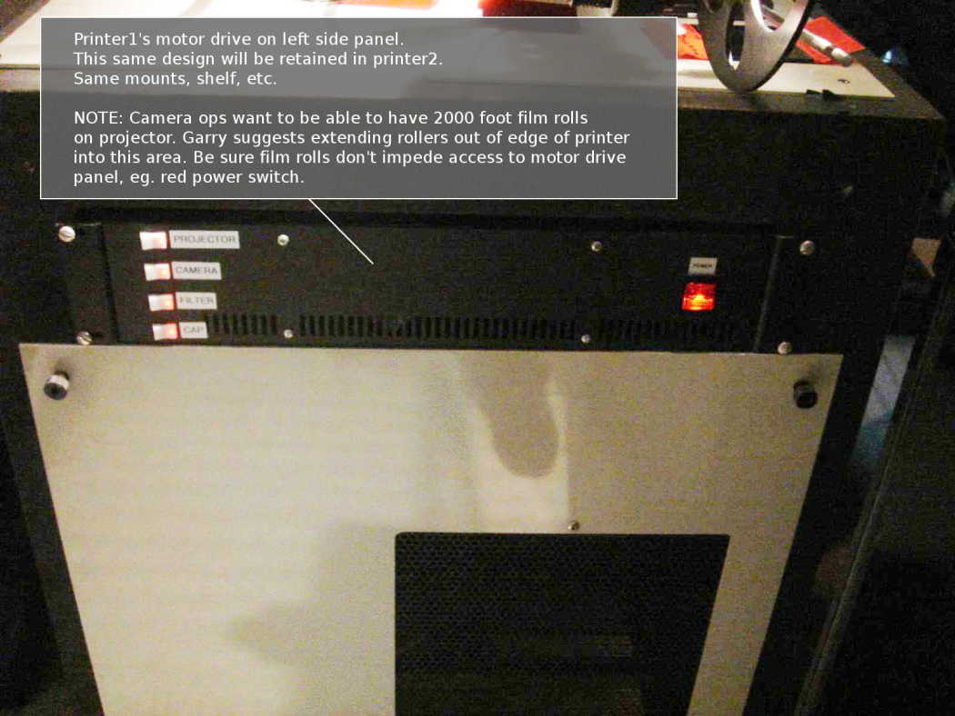
printer1-side-panel-motor-drive-front.jpg
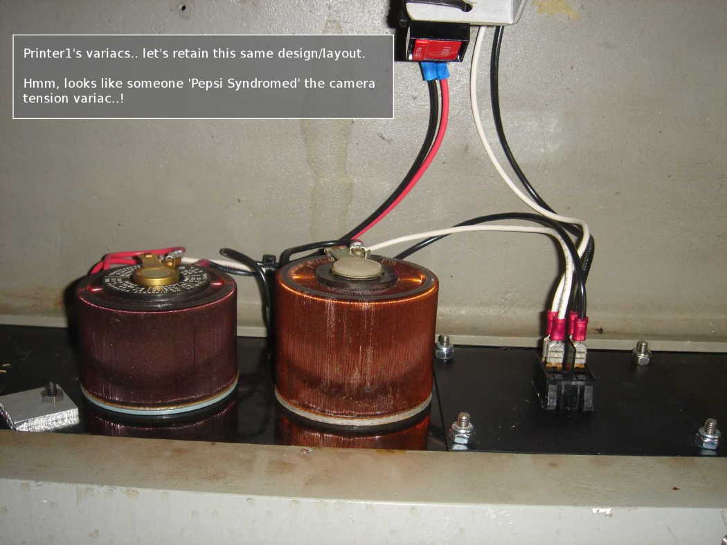
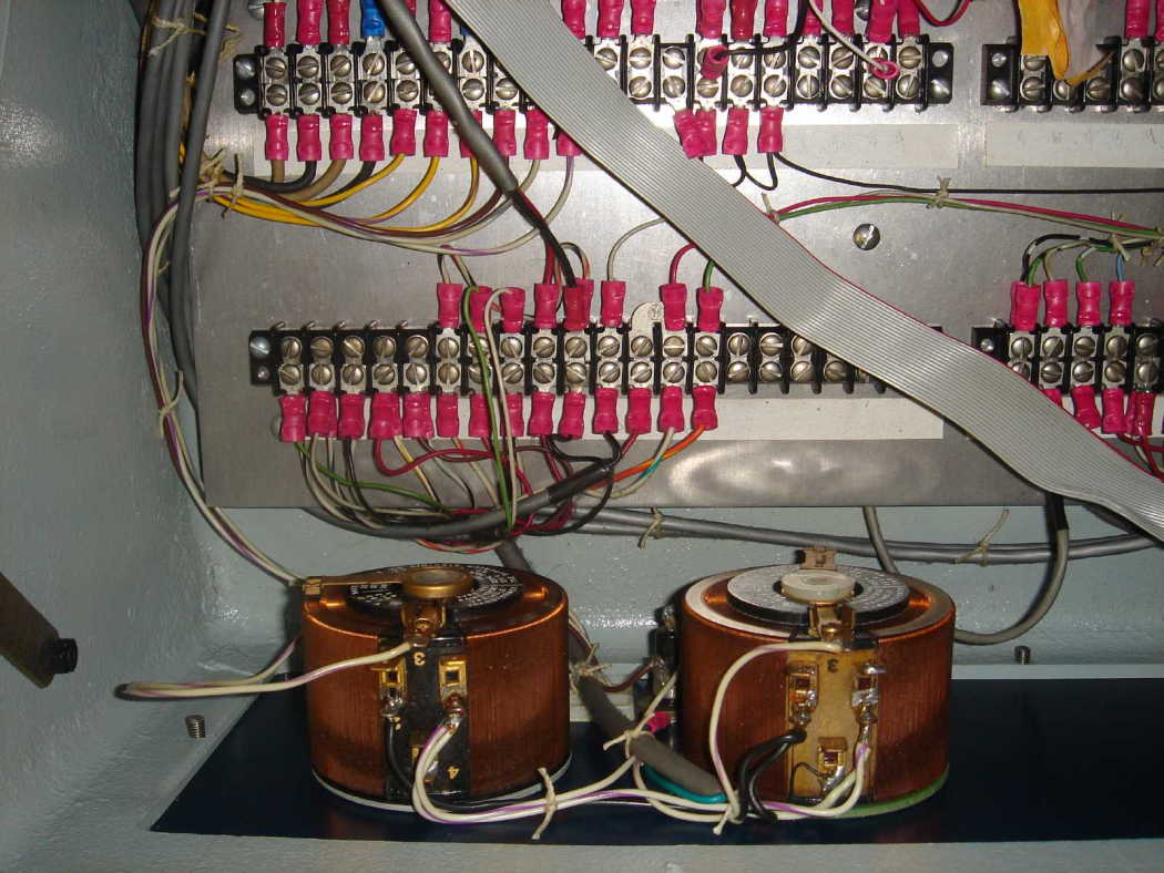
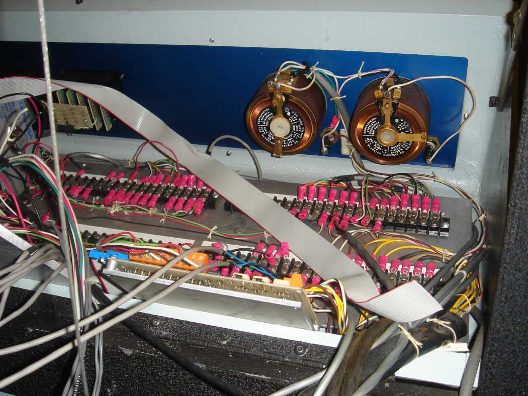
printer1-variacs-back.jpg
DPDT switch (right) is the back of the green "0/1" rocker switch
on the front panel that disconnects power to tension motors/variacs.
