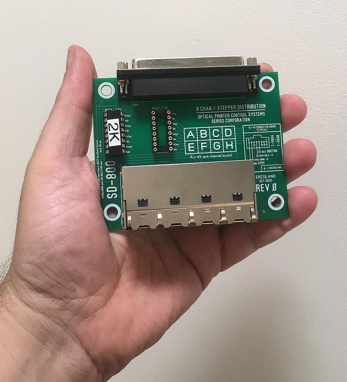
The SD-800 breaks out the steps/direction signals from Kuper RTMC16, RTMC48, and OPCS A800 on a DB37 connector
into separate RJ-45 connectors. This simplifies wiring of step/direction signals between these cards and the stepper motor drive modules.
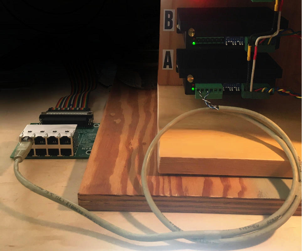
RJ-45 cabling makes it easy to swap or reassign motors to different channels, and to modularize each channel for maintenance.
Here's an SD-800 card with just the A channel wired to a stepper drive:
 |
 |
| SD-800's DB-37 connector | SD-800's 8 RJ-45 jacks |
Currently there are only two revisions of this board, REV-0 and REV-A, which are identical except for small silk screen modifications.
What follows are images of the circuit layout layers as they appear in Sprint6 Layout and/or a Geber viewer (such as the open source tool 'gerbv'), along with board mounting dimensions.
 SD-800 top and bottom layer (click for full sized image) |
 SD-800 board mounting dimensions (click for full sized image) |
 SD-800 top layer |
 SD-800 bottom layer |
 SD-800 photo top side |
 SD-800 photo bottom side |
 Sheet 1 of 1 (click for full sized image) |
Use cable strain relief when possible for the DB-37 cable, to prevent tugs on cabling from stressing the DB37 connector on the SD-800 card.
When wiring the RJ-45 cables to the stepper drives, follow the wiring diagram in the above schematics.
The SD-800 has only one configurable option: the resistor networks RN1 and RN2 which should be configured as follows:
When installed, they pull up the steps/direction outputs to +5, which for open collector outputs can decrease noise pickup when these signals are floating. Noise can cause motors to creep, or run erratically and loose position. Example: moving only channel B in reverse may cause neighboring channels A or C to creep or run improperly, or the moving channel B may not run correctly and loose position.
When you're experiencing noise problems during testing, install the SD-800's 1K pullup resistors in RN1 and RN2. If noise problems persist, use a scope to check the step/direction signals at the motor drives. You should see the "steps" signal to normally reside at +5v, and fall to ground during stepping. The "direction" signal should either be +5v or GND during motor running, and not some value inbetween.