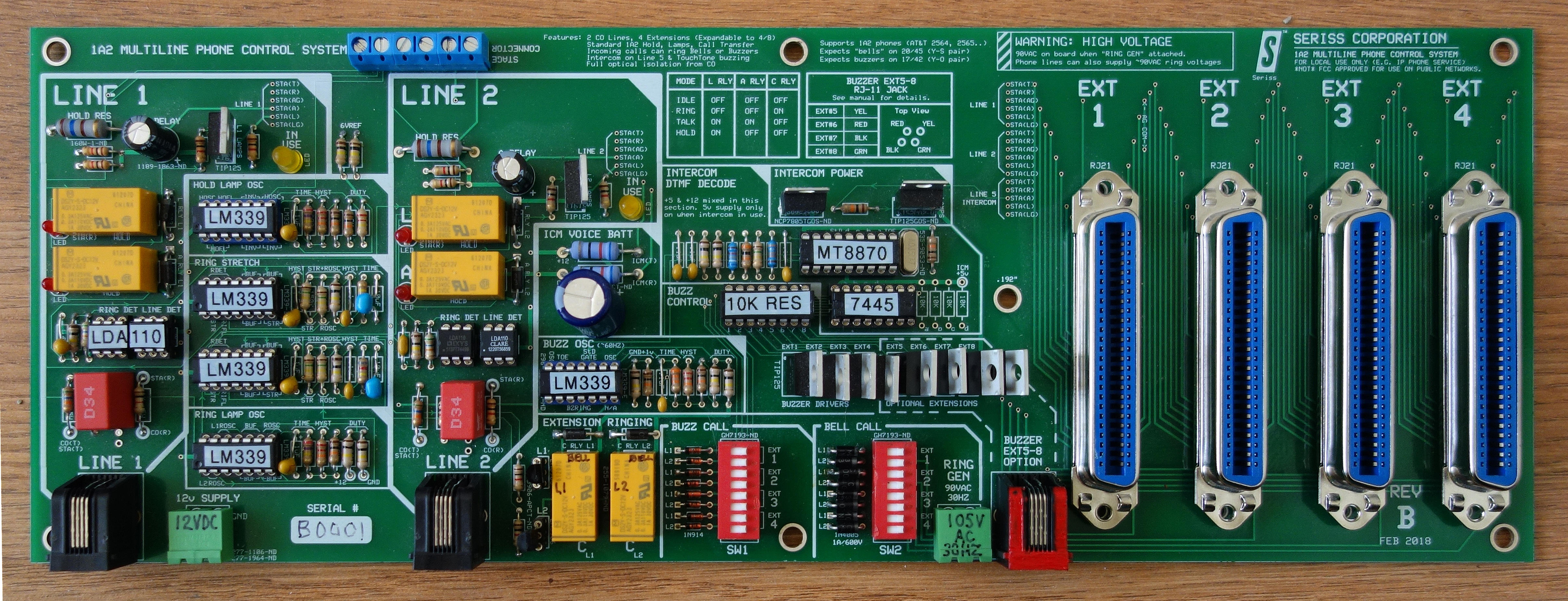
1A2 Multi-Line Telephone Control Board (REV B).
Supports 2 lines, 4 extensions, standard 1A2 features for ringing, Intercom with dial-pad buzzing.
 |
[Update: Oct 1, 2019: There is a newer version of this project which covers the latest features and progress of this project, and I sell as an actual "product". I've been selling the assembled boards in small quantities to people who inquire to my email address, erco@seriss.com. Please include "1A2 multiline phone card" as the email subject.] |
This board was a personal weekend project in the mid 2000's that turned into a full on serious endeavor that ended up as a somewhat professional board. This board controls old 1A2 multi-line business telephones that were made available by the AT&T / Bell Telephone company during the 1960s through the mid 1980's. It can operate their standard features, interfacing them to modern phone lines, either PSTN (Publicly Switched Telephone Networks), or the more popular modern VoIP systems offered by most phone and cable providers, which usually include an interface box for regular phones.
Basically this is a "single board KSU" (Key System Unit), similar in function to what the original AT&T 551a KSU “shoebox” does, but small, light, and with some added features. Uses a simple 12v DC/1.5A power supply (wall wart) to operate all features of the phones, including lamps, buzzers, and ringers. The board provides standard 50 pin Amphenol (or “Telco 25 pair”) connectors on board, allowing phones to either be directly plugged in (for demos), or to long Male-to-Female CAT3 extension cables for an actual home or office setup with remote extensions.
This board provides the usual 1A2 features, plus some extras:
Just add a 12v supply, some 1a2 phones, attach to POTS compatible phone lines, and it should all work.

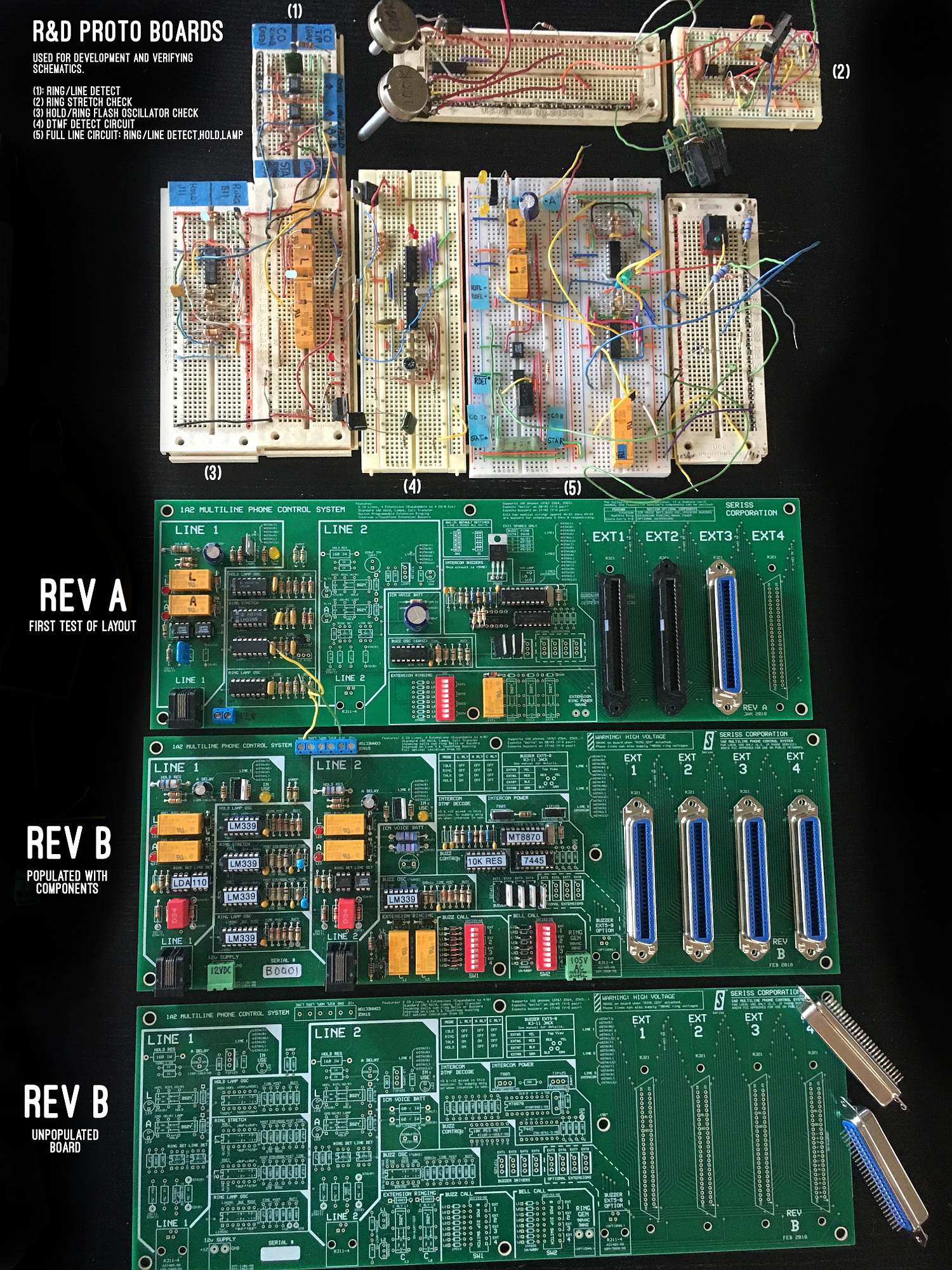
Why do this? To bone up on analog circuit design. It was a design goal to NOT use computers on this project (no PIC chips, Arduino, Raspberry Pi, etc), and use only chips/techniques available from around the 1980s. Presented below are the schematics, board design, circuit description, and user's manual, so that one can print and build these boards on their own like I did.
I heavily referenced the Bell System Practices manuals (BSP), books on telephone design, line card patents, and various sources on the web for old phone equipment. Also studied vintage equipment from the period these phones were popular; an AT&T 551a KSU, 400D line cards, ComKey 416 phones. When I ran into trouble with analog design issues, I often conspired with a friend well versed in EE and analog circuit design who kept me on the right track.
Here's a shot of an early prototyping board circuit, along with REV A and REV B versions of the board:

 |
 |
 |
The ExpressPCB software is great for people who dabble in board design like myself. It's VERY easy to learn, use, and makes it easy to quickly print boards and have them delivered, without having to know anything about gerber files and such. Just lay it out, and choose the "Order" option, and they take your credit card + address, and and send you the printed boards, typically within 1 week.
The catch with using this free software is you are locked in to having the boards printed at expresspcb.com, and their cost for printing boards is a bit on the high side compared to other board printing services. But, given how incredibly hard other board layout software is to use (KiCad, Eagle..) it's kinda worth it. Making components in KiCad is painful
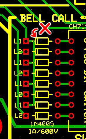 REV B - diodes in wrong direction
 |
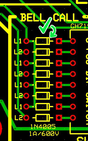 REV B1 - diodes in proper direction |