1A2 Phone System Description
============================
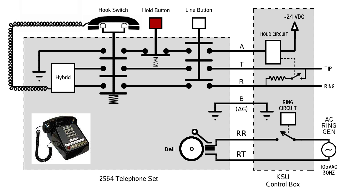
This diagram a simplified view of a typical 1A2 phone system; a single phone line
coming into the KSU (Key System Unit) Control Box (at the right) connected
to one of the 5 lines on a single phone set (an AT&T 2564) at the left.
An actual 2564 phone set manages 5 separate lines, but each of the 5 lines
is handled the same way, so for simplicity we're only showing one of the 5 lines.
The major 1A2 control signals are shown:
"T" (Tip) and "R" (Ring) are the wires from the phone company,
"A" (the "A" lead) indicates a line has been picked up,
"B" (Battery) is ground for all the line's A lead.
The connector pinout for these signals for Line #1: A is pin #27, T is pin #26,
R is pin#1, B is pin #2 (and is the common ground for ALL the line's A leads).
Also shown are the RR and RT ringer signals which the KSU will supply AC power to
when it wants to ring any phones programmed to ring when a call comes in on this
line. Unlike normal phones, 1A2 phone's ringers are NOT connected to the T/R signals;
this is so that the KSU can cause the phone to ring from any line, and so the
KSU can program which phones ring on which lines. The ringer pair is almost always
on the Yellow/Slate pair (pin #20/#45).
Not shown in this diagram are the wiring of the line lamps (usually labelled "L").
Suffice it to say that each Line Button has a lamp under it that the KSU can control,
and a simple circuit in the KSU gives 10VAC to the lamp to light it up; the lamp
usually either blinks at a steady rate for an incoming call (ringing), or "winks"
when a call is on hold, or stays on when a call is in progress, and is off when the
line is idle.
The "Tip" and "Ring" at the far right are the phone lines directly from
the phone company/central office (CO).
The state of the phone set shown in this diagram is with the phone 'on-hook'
no line selected. Here's a simple animation showing the phone in the
various states for a phone call; (1) on-hook/at rest, then (2) someone picking
up the receiver (off-hook), then (3) selecting the line, and finally (4) hanging up
(back "on-hook").
RING
If a call were to come in, the KSU would ring all the phone sets whose
ringers are programmed to ring. The KSU will also blink this line's lamp
on all the phone sets with access to this line. This way someone looking
at the phone can tell which line is ringing, and answer it.
The lamp will blink at a rate of 1 second: 1/2 sec "on", 1/2 sec off.
ANSWER
To answer an incoming call, push the blinking line and pick up the handset.
Same for picking up a call on hold.
When the line button is selected, this closes all the terminals in the
line button's switch. And when the receiver is lifted, this closes
all the terminals in the "Hook Switch", grounding the A lead as a way
to signal the KSU the line was selected.
With the two multipole switches closed, this will:
1) Ground the "A" lead (used by the control circuit to determine a line in use)
2) Connect Tip and Ring from the phone company to the phone's voice circuit (the "hybrid")
When the voice circuit is placed across Tip and Ring, the phone company
sees this and stops sending the ring signal, and connects the call.
In this state, the KSU turns on the lamp light (no blinking) for this
line on all the phone sets that have access to this line, giving a visual
indication the line is "in use".
In general, the phones are all wired in parallel; all the line lamps,
A leads for each line, and Tip and Ring for each line all go out to
the sets the same way; if line 1's lamp is lit, it's lit on all phone's
line 1. (The exception is if the sets are programmed differently for
special use)
HOLD
To put a call on hold, press the "Hold Button".
While the button is down, this disconnects the "A" lead from ground, but
keeps the talk circuit for the phone engaged (unlike a hangup which
disconnects both at the same time). This causes the KSU control circuit
to realize someone pushed the Hold button, causing it to short a resistor
("hold resistor") across Tip and Ring, effectively putting the
call on hold.
When the Hold Button is released, it mechanically releases which ever
line button is down on the set, removing the talk circuit from Tip and
Ring. The call is now on hold -- the phone company sees current flowing
through the "hold resistor", and keeps the call connected. (The hold
resistor simulates the current flow through the phone's voice circuit,
such that the phone company keeps the call active)
Optionally, the KSU may connect 'music on hold' to Tip and Ring via
a voice coil/isolation transformers (in place of the hold resistor)
for any calls that are on hold. This gives an audio indication to the
person on hold that they are on hold, and weren't hung up on.
When a call is on hold, the KSU "winks" the line's lamp (2 blinks per
second, 80% duty cycle) on all the phone sets that have access to this
line, visually indicating that line has a call on hold.
At this point any phone set with access to the line can pick up
the call, causing the KSU to disconnect the hold resistor from
across the line, and stops the winking lamp, returning the lamp
to "steady on".
If the person on the other end hangs up while the call is on hold, the
phone company will drop the call, opening Tip and Ring briefly (zero
voltage) which causes the KSU to disconnect the hold resistor,
extinguishing the lamp, and freeing up the line.
HANGING UP
To hang up the call, put the receiver back in the cradle. This causes
the "Hook Switch" to open all its terminals:
1) disconnecting the phone's voice circuit from T and R
2) disconnects the "A" lead from ground
..effectively hanging up the call. The KSU will turn off the lamp
for that line on all phone sets with access to the line, indicating
the line is available for use.
MORE ABOUT "HOLD" -- HOW TO TELL "HOLD" FROM "HANGING UP"
The "A" lead signal changes from ground to an open circuit in two situations:
1) When someone hangs up
2) When someone presses the Hold button
The only difference is that when someone hangs up, the A lead
and T/R signals are all disconnected at the same time, due to the ganged
contacts of the hook switch.
Whereas, when someone pushes and releases Hold: while Hold is pressed,
the A signal is disconnected but Tip and Ring are still attached to
the voice circuit (the line button remains down) keeping the call active.
This triggers the hold circuit to place a resistor across Tip and Ring
(the "Hold" resistor), which will keep the call on hold. Then when the
Hold button is released, the mechanics of the Hold button release the
selected line button, disconnecting the phone's voice circuit, releasing
Tip and Ring from the phone. The hold resistor now keeps the call from
dropping until someone picks up the line.
This small delay between A becoming open and Tip and Ring being released
are the basis for detecting the difference between a Hold and Hang Up
condition. How this is done varies based on the hold circuit in the
KSU's line cards.
The detection has to be done within a short time window, roughly 1/10th
of a second; quickly enough to happen before the user releases the Hold
button, but not so quickly as to mistake the small delays in the hook
switch contacts opening (when someone hangs up) for a Hold condition.
If the Hold circuit delay is too slow, the call can be dropped when
someone presses/releases Hold quickly. Too fast, and the call might
accidentally go on Hold when someone hangs up slowly. (The hook switch's
mechanics should prevent this)
This is why it's possible to drop a call if one pushes + releases the
Hold button too quickly; the Hold circuit will think it's a hangup
when the line buttons pop up to quickly, dropping the call.
It is for this reason (I think) that the Hold button mechanics are
loaded with a very strong spring, making it hard for someone to
press and release it too quickly.
MULTIPLE PHONE SETS
The above diagram is a simplification in that it shows only one line
on a single phone set.
But in a 1A2 phone system, each set will have several lines, and the
sets are all usually wired together in parallel.
Still, the above description applies even in the presence of many phone
sets, since all the sets operate the same way.
In a simple configuration, let's say there's two incoming lines and 10
phone sets. This means there will be two line cards in the KSU, one to
manage each line. And let's say the KSU is wired so that all 10 phones
can access both lines.
The phone's lamps, A leads, and Tip and Ring will all be wired in parallel;
if any A lead on line 1 is grounded at a phone set, the KSU sees the A lead
for that line grounded.
If a call comes in on line #1, all phones will show line #1 blinking
because the line 1 lamp on all phones are wired together in parallel.
Every phone's line 1 lamp blinks. And one or more people can pick up
line #1 because the Tip and Ring wires are also wired in parallel.
At the KSU, each line has its own 'line card' which handles the four
different states for that line:
1) Idle
2) Ringing (incoming call)
3) Answered/in use (off hook)
4) On hold
The one line card only manages a single line. The KSU must contain
at least one card for each incoming line from the phone company.
The lamps on 1a2 phones give a visual indication for each line's
state:
1) Idle -- lamp is off
2) Ringing -- lamp blinks at 1 flash per second, 50% duty cycle (500ms on/500ms off)
3) Answered/In Use -- lamp stays on
4) On hold -- lamp "winks" at 2 flashes per second, ~80% duty cycle (400ms on, 100ms off)