
THE BELL SYSTEM
Technical Journal
DEVOTED TO THE SCIENTIFIC AND ENGINEERING ASPECTS OF ELECTRICAL COMMUNICATION
VOLUME XXXIX
JANUARY 1960
NUMBER 1
Pushbutton
Calling with a Two-
Group Voice Frequency Code
L. SCHENKER
NOTE:
This document is the result of scanning a copy of the original
publication and then converting the scanned images to text using
Optical Character Recognition (OCR) software (OmniPage Pro Version
11). Although the OCR results were compared manually with the
original document to find and correct any errors created by the OCR
software, no guarantee is implied as to the accuracy of this
document. Also, outdated terms and abbreviations are followed by
[bracketed] modern terms or abbreviations (i.e., cps [Hz].) A big
thanks to Jodd Readick for sending me copies of the original document
for me to scan and convert to text files. - David Massey
[EDIT 10/17/2022] Some error fixes and more unicode entities and subscripting applied. -erco@seriss.com
This electronic document was created from scans of the original
paper document by David Massey and appears on his website, the Bell
System Memorial at
www.BellSystemMemorial.com.
COPYRIGHT 1960 AMERICAN TELEPHONE AND TELEGRAPH COMPANY
A customer voice frequency pushbutton signaling scheme involving a new two-group signal code, termed "four-by four", is described. It is shown that the use of this code, with judiciously chosen frequencies, permits the detection of bona fide signals after transmission over any ordinary voice connection and facilitates discrimination against false signals resulting from speech. Apparatus for generating the tones is described, and the principles of reception are discussed.
I. INTRODUCTION
In recent years, customer signaling from a telephone set by means of pushbuttons has appeared increasingly promising. An early plan has been reported' in which the operation of a pushbutton produces four effects: (a) the generation of a damped oscillatory wave at one of ten digit-identifying frequencies within the voice range; (b) the generation of a similar damped wave at one of eight party-identifying frequencies, also in the voice range; (c) a stepwise reduction of the direct current drawn by the set and (d) the temporary disablement of the speech transmitter. Actions (c) and (d) provide protection against talk-off, i.e., false signaling due to speech or noise at the transmitter.
This plan contemplated only the transmission of information to the central office, but in the long run it would be advantageous to be able to signal "end-to-end," over any established connection that will transmit speech. With this added objective several new considerations are introduced. Clearly, the signals should not contain an out-of-band component such as the do step. Again, there may be a need for more than ten distinct signals, and these may be difficult to provide in a scheme based on a one-out-of-N code, for a new frequency must be added for each new signal. On the other hand, party identification would not be a feature of end-to-end signaling. Lastly, sustained rather than damped signals are strongly preferred for end-to-end signaling, in order to maintain adequate signal-to-noise margins despite wider ranges of transmission loss.
Voice-frequency signaling as such is, of course, already an established practice in the Bell System. One example is multifrequency key pulsing2 (MFKP), which is widely used for toll signaling. However, minimization of talk-off was not a factor in its development, and tolerance of considerable carrier shift was one of the prime objectives. Another example is in-band single-frequency signaling3, which is used in the long-distance telephone plant for transmission of supervisory and dial signals.
This paper describes an all-voice-frequency signaling system that provides substantial protection against talk-off. It is based on a two-group arrangement commonly called the "four-by-four" code. Field and laboratory tests of the signaling system have been encouraging, and user reaction to pushbutton operation during a trial involving some 400 customers has been favorable.
II. CHOICE OF CODE
When only voice frequencies are employed, protection against talk-off must rely heavily on statistical tools. This protection is required only during interdigital intervals; speech interference with valid signals is conveniently avoided by transmitter disablement. Since signals with a simple structure are prone to frequent imitation by speech and music, some form of multifrequency code particularly difficult of imitation is indicated. If the signal frequencies are restricted in binary fashion to being either present or absent, the greatest economy in frequency space results from the use of all combinations of N frequencies, yielding n = 2N different signals. However, some of these are no more than single frequencies and are therefore undesirable from the standpoint of talk-off. Another drawback is that as many as N frequencies must be transmitted simultaneously; these involve an N-fold sharing of a restricted amplitude range, and may also be costly to generate. If n > 10, N would need to be at least four. At the expense of more frequency space we are led to a P-out-of-N code, yielding n = N!/P!(N - P)! combinations. There is statistical advantage in knowing the number, P, of components in all valid signals.
In order to minimize the number of circuit elements,** as well as to reduce the sharing of amplitude range, P should be as small as possible, yet be larger than unity for the sake of talk-off protection. Let us then examine codes in which P = 2. If one can be found that is not readily imitated by speech or music, there is no merit in choosing P higher than two, provided that the total number of frequencies N needed for the required number of combinations can be accommodated in the available frequency spectrum. With P = 2, N must be at least five to provide ten combinations (for the ten digits). With N = 6, 15 combinations are available. The familiar MFKP signaling scheme makes use of a two-out-of-six code.
There are advantages, as we shall see, in imposing the further restriction that, with P = 2, the frequencies for each combination fall respectively in two mutually exclusive frequency bands. If, for example, 15 combinations are required, N must be at least eight (giving 16 combinations). In the four-by-four code, eight signal frequencies are divided into two groups: group A, the lower four frequencies, and group B, the upper four. Each signal is composed of one frequency from group A and one from group B.
III. BAND SEPARATION AND LIMITER ACTION
With a group arrangement, it is possible at the receiver to separate the two frequencies of a valid signal by band filtering before amplification or determination of the specific components. This separation of the two components of a signal renders reliable discrimination between valid signals and speech or noise simpler for two reasons: (a) each component can be regulated separately, thus compensating for "slope," the differential transmission loss incurred by the two components, and (b) an instantaneous extreme "limiting" can be applied to each component after band separation, and thus provide a substantial guard action.
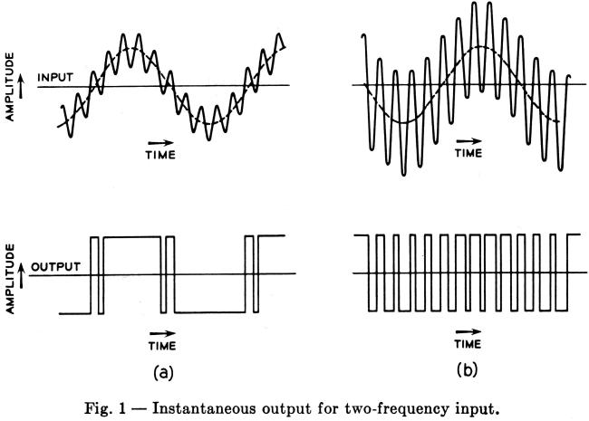
It is a characteristic of extreme instantaneous limiters that they accentuate differences in levels between the components of a multifrequency signal. This may be used to provide guard action, that is, action to reduce the probability of false response to speech or other unwanted signals. Fig. 1(a) shows the input and output of such a limiter with an input signal composed of two frequencies. The lower frequency (dotted line) has the larger input amplitude. Assuming infinite gain, the limiter output may be constructed from the axis crossings of the input. The higher frequency produces some interference, but the low frequency dominates in the output. In this example, noise could be substituted for the higher frequency. In Fig. 1(b) the higher frequency has the larger amplitude and dominates in the output.
* It is here assumed that the P components are simultaneously produced in P resonant circuits, at least one of which can be tuned to each of the N possible frequencies.
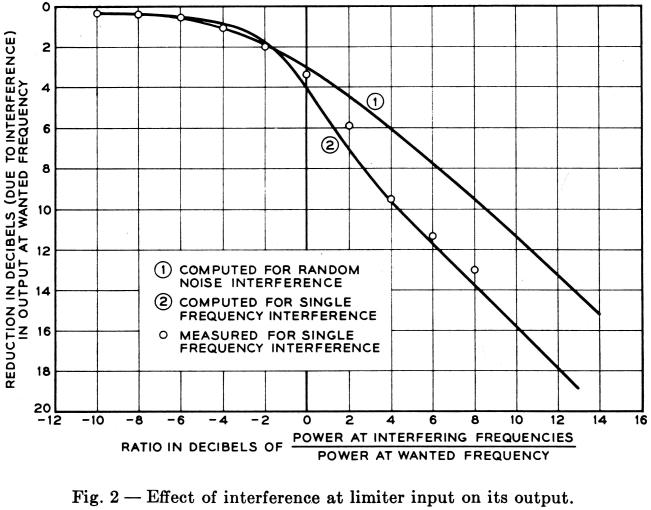
Quantitative relationships are shown in Fig. 2, where the abscissa is the ratio at the limiter input of the power in the interference to the power at the wanted frequency, and the ordinate is the power at the wanted frequency at the limiter output relative to its value in the absence of any interference at the input. Curve 1 is for the case where the unwanted component is random noise; curve 2 applies where the unwanted component is a single frequency, not a harmonic of the wanted frequency. (The mathematical analysis leading to these results was made by S. O. Rice.) Experimental results are also shown for the case of a wanted frequency of 900 cps [Hz] and an unwanted frequency of 500 cps [Hz].
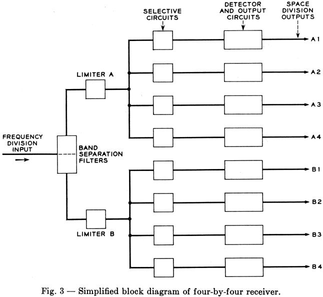
What is the significance of the data shown in Fig. 2 with respect to guard action? Speech may contain components which simulate proper signals, but it is likely to include energy at other frequencies also. The selective circuitry that follows the limiter is designed to recognize a signal as bona fide only when it not only falls within a rather narrow passband, but also appears at an amplitude within about 2 ½ db of the full output that the limiter is capable of delivering. Thus, when a burst of speech contains components at more than just the two signal frequencies, this fact is used to inhibit recognition of the signal frequencies in the burst. Inspection of Fig. 3, a simplified block diagram of the receiver, may be helpful at this point.
Aside from considerations of guard action, it is interesting to note that, in divesting signal tones of amplitude variations, a limiter endows a selective circuit with an appreciably higher degree of selectivity than would normally be associated with the selective circuit's response characteristics. Thus, simple tuned circuits can adequately perform the function of frequency discrimination. An incidental by-product of this feature is that the response to tones with frequencies just outside the range recognized as valid is only moderately less than the response to valid tones. Consequently, sidebands associated with pulsing rates are only slightly attenuated and no specific allowance need be made for them in selecting the spacing between signal frequencies. G. C. Prins has taken advantage of this property for the control signaling for TASI, * in which a four-byfour-by-three code is used.
Guard action of the type that has been discussed requires that only one of the two tones making up a valid signal be admitted to each limiter. In order to derive the full benefit of limiter guard action, as much of the speech spectrum as possible should be given access to the limiter. Clearly, a bandpass filter preceding the limiter, to separate the two components of a valid signal, would defeat this objective, since it would permit competition for limiter capture between a signal frequency and only that portion of the speech burst lying in the same band (A or B). On the other hand an elimination filter allows competition with the whole speech spectrum except the attenuated band (B or A). Suitable characteristics for the band elimination filters are shown in Fig. 4.
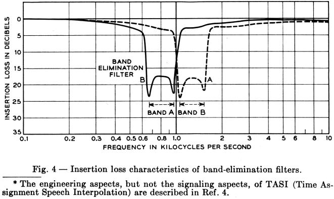
The loss in the elimination band is more than 17 db. It will be shown that the two components of a bona fide signal differ at most by 5 db; consequently the interfering effect at the limiter input of the complementary component is never greater than that of an unwanted signal 12 db below that at the wanted frequency. It may be seen from Fig. 2 that the effect of noise 10 db or more below the signal is insignificant.
The fact that the band-elimination filters provide discrimination no greater than 17 db or so is advantageous in that guard action is still effective when an unwanted signal speech or music contains two major components at frequencies essentially the same as in a bona fide signal, but with amplitudes that differ by 17 db or more. Even in the absence of any other speech energy, the stronger component, although attenuated by the filter, would have at least the same amplitude as the weaker component at one of the limiter inputs, with the result that the limiter output would be reduced by 3 db, which would prevent recognition.
It may be desirable under some circumstances to increase the extent of guard action. This can be achieved by placing an equalizer ahead of the two band-elimination filters. Pre-emphasis of frequencies outside the signaling range enhances guard action. A speech burst containing two proper signaling frequencies might be registered as a valid signal if there is an insufficient aggregate of power at extraneous frequencies to invoke limiter guard action. Statistically, there are borderline cases where enhancement of these extraneous frequencies will tilt the balance. The practical limit to this procedure is set by system noise levels, which would also be enhanced and which would eventually tend to prevent the recognition of bona fide signals.
IV. CHOICE OF FREQUENCIES AND AMPLITUDES
4.1 Frequencies
Attenuation and delay distortion characteristics of typical combinations of transmission circuits are such that it is desirable to keep a multifrequency signal system within the 700 to 1,700 cps [Hz] range,
The choice of frequency spacing depends in part on the accuracies of the signal frequencies. It is expected that signals generated at the station set will be within 1.5 per cent of their nominal frequency values, and that the pass bands of the receiver selective circuits can be maintained within 0.5 per cent of their nominal ranges. (The basis for these estimates is discussed later.) Consequently, the selective circuits of central office receivers need to have recognition bands of ±2 per cent about the nominal frequencies. In the case of receivers designed for end-to-end signaling, additional tolerance will be needed to accommodate the frequency changes introduced by carrier shift in some toll systems. Large frequency shifts are introduced only by the nonsynchronized systems (C, H and J), and even here the increasing use of voice-frequency telegraph and telephone signaling puts a premium on closer limits. Tentative requirements of 4-10 cps [Hz] of carrier shift were adopted for the signaling system described here.
The standardization of amplitude brought about by limiting permits an accurate definition of recognition bands in the receiver, irrespective of loop losses or slope. Judicious use of timing-namely, in delayed scanning of the selective circuit outputs-minimizes the effects of transient components upon adjacent channels. As a result, frequencies may be spaced quite closely, approaching, in fact, the recognition bandwidth of 4 per cent + 20 cps [Hz]. If the lowest frequency is chosen as 700 cps [Hz], the next frequency must then be more than 748 cps [Hz], which is 7 per cent higher. Another 1 or 2 per cent increase in spacing makes the precise maintenance of the bandwidth less critical.
Another factor can profitably be taken into account in the selection of a frequency spacing. To reduce the probability of talk-off, the combinations of frequencies representing bona fide signals should be such that they are not readily imitated by the output from the speech transmitter. In a receiver with the guard action described, no sound composed of a multiplicity of frequencies at comparable levels is likely to produce talk-off. Thus, consonants present no problem. Vowels do, however, as do single-frequency sounds such as whistles that are large enough to encounter some harmonic distortion in a carbon transmitter. Fletcher6 has shown that an electrical analog of the mechanism involved in the articulation of vowels is a buzzer (the vocal cords producing a fundamental and a long series of harmonics) followed by a selective network that shapes the harmonics into "formants" of the vowel sound. As a result, the spectrum of any sustained vowel contains a number of frequencies bearing harmonic relationships to each other. Hence, it is desirable that the pairs of frequencies representing valid signals avoid as many of these harmonic relationships as possible. The number of undesirable combinations is large but finite. Considering harmonics based on fundamental frequencies down to 100 cps [Hz], there are about 65 combinations that fall into the 700 to 1700 cps [Hz] range, with one frequency below and one above the geometric mean of 700 and 1700 cps [Hz].
A family of frequencies that avoids a large proportion of troublesome combinations and also meets all the other requirements discussed so far is as follows, the adjacent frequencies in each group being in the fixed ratio of 21:19, with one-and-a-half such an interval between the groups
Group A Group B
697 cps 1,094 cps
770 1,209
852 1,336
941 1,477
All frequencies are essentially within the 700 to 1,700 cps [Hz] range, and the spacing is adequate to accommodate the recognition bands. The 16 pairs of frequencies representing valid signals avoid low-order ratios.
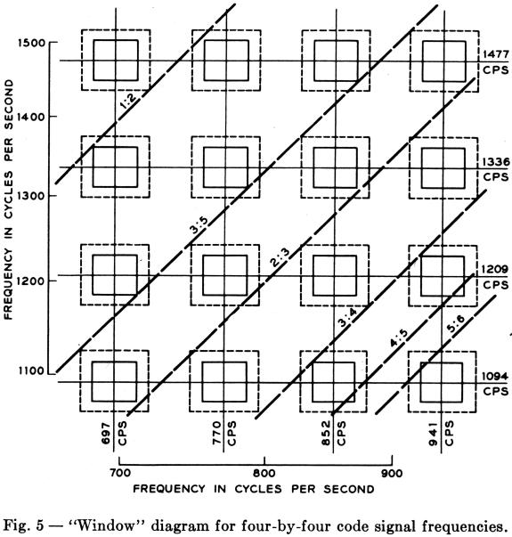
This is illustrated in Fig. 5 where frequencies are plotted on two logarithmic scales: those below 1,000 cps [Hz] as abscissae and those above 1,000 cps [Hz] as ordinates. Any valid signal is represented by a pair of coordinates namely, its two component frequencies. The 16 square "windows" represent the ±2 per cent recognition bands required, with no allowance for carrier shift. The rectangles with ±(2 per cent + 10 cps [Hz]) sides represent the recognition bands for receivers involved in end-to-end signaling. The diagonal lines are the loci of pairs of frequencies having simple harmonic relationships, i.e., 1:2, 2:3, 3:4, 3:5, 4:5 and 5:6. The avoidance of these particular diagonals is beneficial, because they represent the effects of harmonics not only of the corresponding order but also of higher order, for example, the third and sixth, the ninth and 15th, etc. Not all applicable diagonals are shown in Fig. 5, and 18 of the 65 potentially troublesome combinations are not avoided. However, if two frequencies in speech representing two fairly high-order harmonics happen to fall at proper signal frequencies, their fundamental will be low in frequency, and the odds are then good that other harmonics within the telephone speech band will, together, have sufficient relative intensity to bring guard action into play.
Obviously, the larger windows needed in end-to-end receivers increase the probability of talk-off from harmonics in vowels.
Comparable benefits with respect to talk-off can be. derived from other sets of frequencies with the same geometric spacing but displaced up or down on the frequency scale. The effect of such displacement is to shift all the windows in a direction parallel to the diagonals.** This specific set of frequencies was chosen because it is interleaved with the frequencies proposed for the tone ringer.1
It may be noted that, although a multigroup code requires a larger number of frequencies than a nonredundant P-out-of-N code, the closer frequency spacing made possible by group separation and limiting can actually result in economy of frequency spectrum.
4.2 Amplitudes
Since signaling information does not bear the redundancy of spoken words and sentences, and yet must be transmitted with a high degree of reliability, the signal power needs to be larger than the average speech power output from a telephone. A nominal combined signal power for the two frequencies of 1 db above 1 milliwatt at the telephone set terminals has been adopted as a realistic value, a ±3 db tolerance about this nominal value being acceptable.
For subscriber loops the maximum slope between 697 and 1,477 cps [Hz] is about 4 db, the attenuation increasing with frequency. In two-subscriber loops (as in end-to-end signaling) the slope may be 8 db, although statistically this is unlikely. A reduction in the maximum amount of slope can be achieved by transmitting the group B frequencies at a level 3 db higher than that of the group A frequencies. In this way the amplitude difference at the receiver input between the two components of a valid signal is never more than 5 db, and rarely more than 3 db. The nominal output powers are chosen as -3.5 dbm and - Z dbm for groups A and B respectively, adding up to +1.3 dbm. In more than 99 per cent of station-to-central-office connections the 1,000 cps [Hz] loop loss is expected to be less than 10 db (during the early 1960's). Similarly, the station-to-station loss at 1,000 cps [Hz] is estimated to be less than 27 db in more than 99 per cent of all connections. Making some allowance for slope and variations in the generated power, the minimum signal power at a central office receiver is estimated to be -15.5 dbm. At a receiver involved in end-to-end signaling the minimum power is estimated to be -32.5 dbm.

** Raising the frequencies reduces the areas in the rectangles representing carrier shift, but this effect is small enough to be ignored.
V. GENERATION OF SIGNALING TONES
5.1 Circuit Aspects
A circuit devised by L. A. Meacham and F. West for the generation of the four-by-four code dial signals is shown in Fig. 6. Variations of this circuit are also under consideration, but the version in Fig. 6 is most easily described.
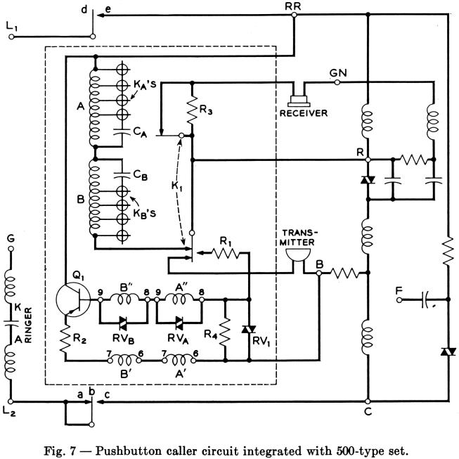
As a practical matter, numerous advantages arise out of the integration of the pushbutton dial circuit with the speech network of the 500type telephone set. This may be done without any modification in the existing speech networks. The integrated circuit is shown in Fig. 7.
Operation of any pushbutton results in the generation of two tones, which last as long as the button is held down. While a button is depressed the speech circuit is disabled. Such performance is achieved as follows
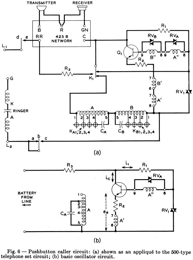
There are two tuned circuits, each consisting of a three-winding coil (A, A', A" and B, B', B") and a tuning capacitor (CA and CB). Windings A and B have a number of taps. The operation of a pushbutton results in the actuation of three switches, one of the KA's and one of the KB's (early in the button stroke) and, lastly, the common switch, K1. In Fig. 6(a), K1 is shown in the normal (speech) condition. In this condition, most of the direct current drawn by the speech circuit flows through a diffused junction silicon varistor RV1 and some through windings A and B. The direct current through RV1 is more than 15 milliamperes, and under this condition the ac resistance introduced in series with the loop is less than 3 ohms and has a negligible effect on the transmission of speech. The forward drop of the diode is stabilized at about 0.6 volt.
When a pushbutton is operated, the closure of one of the KA and one of the KB contacts connects each tuning capacitor to one of the taps on the associated tuning coil. Resonant frequencies are thus established for each tuned circuit, corresponding to the digit signal to be transmitted, but no signal is as yet generated. In the latter part of the travel of the button, switch K1 is actuated through a mechanism common to all buttons. This produces three results: (a) The direct current through the main windings A and B is interrupted, causing shock excitation of the two tuned circuits. (b) The speech circuit is almost short-circuited (the resistance Of R3 is low, but so chosen that the subscriber hears the outgoing signal at a low level). There is, therefore, no appreciable interference from the speech transmitter while a signal is going out. (c) Voltage is made available to the transistor. Having been started at full amplitude, the two-frequency oscillation is sustained by feedback through transistor current multiplication and transformer action between the secondary and tertiary windings of each coil.
The operation of the oscillator is more readily apparent from Fig. 6(b), which shows the circuit in the signaling condition, but omits for clarity the elements of one of the two tuned circuits. It may be shown that this is a bridge-stabilized oscillator' employing a T network bridged by mutual inductance.
The bias for class A operation of the transistor, provided by the resistor R1 and the silicon varistor RV1 , results in a constant direct emitter current. This current need only slightly exceed the peak alternating current, and is preferably kept small to minimize collector dissipation; there is no reason for allowing it to go up with collector voltage (on short loops) as it would if a resistance were used instead of the diode. Further, the diode represents a low ac resistance, obviating the need for a bypass capacitor.
The
oscillator action is determined by two key equations, one ensuring
that the feedback loop gain exceeds unity, and the other governing
the amplitude of the oscillation. The first of these equations may be
shown to be:
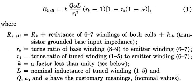
Equation (1) is a modification of the inequality

the significance of which is explained below. The coefficient k is less than unity by an amount sufficient to ensure that the inequality (1a) is satisfied in spite of all admissible combinations of variations in Q, ω, L and α. The physical significance of (1) and (1a) is easily recognized by consideration of the case of rb = 2 and α = 1. Then,

i.e., R2 eff must be less than the impedance seen across the 6-7 winding at resonance. If the peak value of the ac voltage from emitter to "ground" is ee, more than ½ ee appears across the 6-7 winding, and more than e appears across the 8-9 winding, one end of which is grounded through RV1. Neglecting the small ac drop from base to emitter, more than ee appears at the emitter, the assumed starting point. Thus, the loop gain exceeds unity and the amplitude of oscillation must grow until the loop gain stabilizes as a result of some nonlinearity.
Nonlinearity is introduced by means of the silicon varistor RVA, which rapidly reduces Q as soon as the amplitude across its terminals exceeds its forward drop vd, which is approximately 0.6 volt. Since the active element is thus not driven into its nonlinear region, several independent oscillations can be sustained at the same time by the single transistor. Let

Then the peak value of the ac emitter current is given by

From this, rd can be computed to give any desired ie. More exactly, the actual ac voltage-current characteristic of the silicon varistor should be taken into account.
Neglecting leakage, the voltage-current relation for a silicon diode is quite accurately represented by
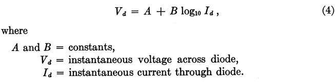
The ac resistance of a diode when it is conducting a direct current Id is found by differentiation of (4). However, in the present application, the voltage-limiting diodes RVA and RVB do not conduct any direct current. F. T. Boesch has shown analytically as well as experimentally that, in this condition (assuming voltage to remain sinusoidal), the relation between the peaks of voltage and current is well approximated by
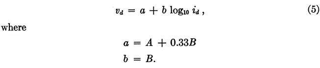
Thus, the effective ac characteristics of the diode can be computed from a measurement of the do characteristics. Substituting the value of vd given by (5) into (3), one obtains

By making use of the various relationships arising out of the transformer and transistor action, id is eliminated from (6) and the second key equation is thus obtained, from which rd can be computed to yield the desired amplitude ie. This is
The equation is not explicit in terms of rd, but yields sufficient accuracy with two or three successive approximations.
The design procedure then is: (a) Select rb. The choice is not very critical. Values of rb between 2 and 5 have been found to result in stable designs. (b) Compute rt from (1). (c) Compute rd from (7). These computations are made at the lowest of the frequencies in each group. The condition for oscillation, (1), is then also met at the higher frequencies of the group.
5.2 Frequency Stability
Owing to the bridge-stabilized nature of the oscillator, many potential sources of frequency instability have a relatively minor effect. Thus, the total change in frequency caused by variations in loop impedance, battery voltage and transistor properties is less than ±0.15 per cent. There remain, however, two major sources of frequency instability: (a) variations in tuning elements and (b) frequency pulling.
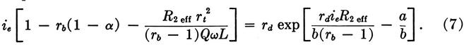
Stability of the tuning elements is, of course, of prime importance. Ferrite cup core inductors offer a combination of advantages not available with other types of cores: good mechanical strength, moldability, simplicity of separately fabricated cylindrical winding, inherent enclosure of the winding, adjustability of inductance and good Q for a given size and stability. Temperature stability and Q can be traded by incorporation of an air gap in the magnetic path with the effect of diluting the inherently high permeability of ferrite, but also diluting the temperature variations in this property.
At audio frequencies the core losses are small compared to copper losses. It is readily derived that, in this range,

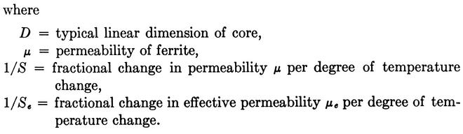
Thus, for a core of given size, D, and of material having given properties µ and S, Q is inversely proportional to temperature stability. For manganese-zinc ferrite, typical values are µ = 1,200 and 1/S = 2,000 ppm/°C. With a core about 1 inch in diameter and 0.5 inch in height, and with an air gap such as to achieve a stability corresponding to 1/Se = 300 ppm/°C, a typical value of Q is 30 at 700 cps [Hz]. Capacitors with polystyrene as the dielectric have a negative temperature coefficient of about -100 ppm/°C, which compensates for part of the change in coil inductance. Frequency variations due to temperature changes over the range from -30°C to +55°C may thereby be held down to less than ±0.5 per cent.
Adjustability of inductance is desirable so that requirements on initial values of the tuning capacitors may be reduced. This is brought about by varying the reluctance introduced by the air gap. In one design, it is achieved by axial motion of a central slug bridging an air gap between the center posts of the two cups. In another design, parts of the center posts are cut away in a manner such that rotation of one cup relative to the other produces a change in reluctance.
In a dual-frequency oscillator with a common active element there exists some "pulling" together of the two frequencies that are generated simultaneously. The presence of the tuned circuit of the second frequency introduces some reactance into the feedback loop at the first frequency. To compensate for the resulting phase shift, the first tuned circuit must go off frequency the closer the two frequencies, the greater the shift. A mathematical study, confirmed by experiment, has led to the following expression for the frequency change:
In the four-by-four code, pulling is worst with the 941-1094 cps [Hz] combination of frequencies. With practical circuit components, pulling for this combination is about 3 cps [Hz] for each of the two frequencies. By changing tap locations, this error can be halved, to become about ±0.15 percent. Except for manufacturing tolerances, there is no other single large source of frequency variations. Considering all sources, it appears practical to hold frequencies within ±1.5 per cent of nominal values; even a ±1 per cent tolerance may eventually be approached.
5.3 Amplitude Stability
The emitter current amplitude is given by (3), and the peak ac collector current is

Since rb and rd are turns ratios, the quantities α, vd and R2eff are mainly responsible for variations in ic. As far as the power delivered to the loop is concerned, further variations are associated with the range of loop impedances.
Whereas it is essential to hold frequencies to values within the recognition band of the receiver, no severe requirements need be set on signal power at the set terminals. Using a precision resistor for R2, but relatively inexpensive units for the amplitude controlling diodes RVA and RVB, power delivered to a 900-ohm loop may vary by up to ±2 db from the nominal values. Differences in loop impedance may introduce an additional variation, but the total is expected to be less than ±3 db. In the case of the circuit shown in Fig. 7, these values are modified by the effect of loop equalization inherent in the 500-type set's circuit.8 This effect is beneficial since on short loops smaller signal amplitudes are not only acceptable but desirable.
5.4 Pushbutton Mechanism
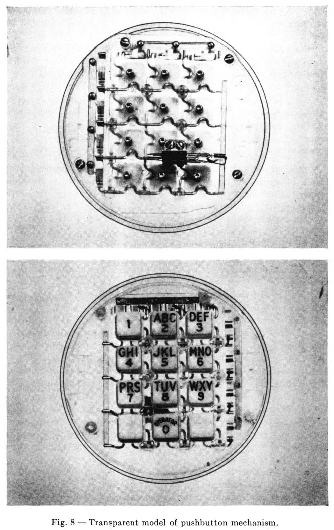
Means must be provided to translate the customer's operation of pushbuttons into the switch operations described earlier, that is, closure of one each of the KA and KB contacts followed by the common switch K1. A mechanism developed by C. E. Mitchell and R. E. Prescott to perform these functions is shown in Fig. 8.
The operation of a pushbutton causes the rotation of two rods, one associated with a row of buttons, the other with a column. The coordinates of a button uniquely determine the pair of rods that rotate when the button is pressed. In the mechanism in Fig. 8, there are four rods corresponding to rows and three to columns. Hence, there are 12 possible combinations of the seven rods; two of these are spares, and the cross-points may not be equipped with buttons. The four-by-four permits an extension of the array, as may be desired, up to eight rods and 16 buttons.
The rotation of a rod closes one of the contacts KA and KB. Moreover, rotation of any of the four rods corresponding to the four rows produces linear motion of the link on the left side of the button array. This link is coupled to a common snap switch performing the function of K1 in Fig. 6 (a). Although not shown in Fig. 8, all signaling circuitry is mounted on the back of the mechanism, making the pushbutton caller a self-contained unit that can be substituted for the rotary dial.
VI. RECEIVER
A detailed discussion of receiver design for this two-group signaling system is beyond the scope of the present paper. However, it seems desirable to touch briefly upon the principles involved, emphasizing those that are directly related to the specific code and frequency allocation of the four-by-four system.
The general requirements to be met are
i. To detect the presence of a bona fide pair of signaling tones in a sufficiently short time that essentially no restriction is placed on the customer's operations or on the pushbutton mechanism to provide delay in release.
ii. To provide the maximum possible talk-off protection consistent with adequate immunity to interference from circuit noise.
Earlier sections have discussed the means employed to optimize detection of valid signals and the guard action inherent in the concatenation of (a) band elimination filters for separation of the two signaling tones, (b) instantaneous extreme limiting of the tones individually, (c) selective circuits passing the fundamentals of these tones after limiting and (d) threshold detection of the response in the selective circuits.
A test for the presence of two and only two tones is a further means for distinguishing between valid signals and others. Part of such a test is provided by limiter guard action: no more than one selective circuit from each group can ever by energized at one time. However, logic must be incorporated to apply the criterion of simultaneous presence of at least one tone in each group.
Recognition time for a valid signal — that is, the time interval for which both components are required to be present without interruption — is an important parameter in receiver design. With the rapid changes that are characteristic of most speech, there is a substantial advantage in making this time as 'long as possible. However, an upper limit is set by the requirement that the system accommodate the most rapid pushbutton operation that a customer is at all likely to attain. A compromise between these conflicting objectives is, of course, necessary. Work to date indicates that the recognition time should be of the order of 40 milliseconds.
VII. ACKNOWLEDGMENT
The names of some — but by no means all — of those who have contributed to the development of the signaling system described in this paper are indicated in appropriate places. The writer wishes to thank these individuals, and particularly L. A. Meacham, who not only made many contributions but also guided the whole project.
REFERENCES
1. Meacham, L. A., Power, J. R. and West, F., Tone Ringing and Pushbutton Calling, B.S.T.J., 37, March 1958, p. 339.
2. Dahlbom, C. A., Horton, A. W., Jr. and Moody, D. L., Applications of Multifrequency Pulsing in Switching, Trans. A.I.E.E., 68, 1949, p. 392.
3. Weaver, A. and Newell, N. A., In-Band Single-Frequency Signaling, B.S.T.J., 33, November 1954, p.'1309.
4. Bullington, K. and Fraser, J. M., Engineering Aspects of TASI, B.S.T.J., 38, March 1959, p. 353.
5. Horton, A. W., Jr. and Vaughan, H. E., Transmission of Digital Information Over Telephone Circuits, B.S.T.J., 34, May 1955, p. 511.
6. Fletcher, H., Speech and Hearing in Communication, D. Van Nostrand Co., New York, 1953.
7. Meacham, L. A., The Bridge Stabilized Oscillator, Proc. I.R.E., 26, October 1938, p. 1278.
8. Bennet, A. F., An Improved Circuit for the Telephone Set, B. S.T.J., 32, May 1953, p. 611.