| Configuring A New Home Sensor | ||
|

| Configuring A New Home Sensor | ||
|
Home sensors are typically the Omron brand, and can either be NPN (the most common) or PNP type. Here is a table of relevant Omron sensor configurations:

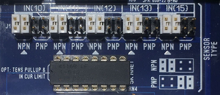
The PIO-100 board supports both NPN and PNP types via the board's J1 jumpers:

It is advised to standardize on one sensor type for all sensors on a single printer, and NPN is the best choice, which is the default configuration. Each optical home sensor can be wired to an RJ-45 patch cable, and plugged into any one of the PIO-100's five RJ-45 input ports:

If plugged into "IN(10)", the home sensor will communicate over the parallel port's computer input pin #10, causing the bit for that port to change state, which can be detected by the 'home' program's 'homeport' command in the HOMEDEFS.HOM file. So if that's configured for e.g. the 'a' channel, typing "home a" would attempt to home the motor and watch for that sensor on pin #10 to change its state.
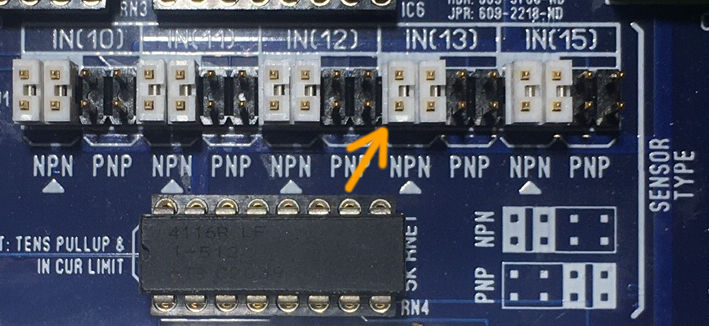
The factory default for all inputs is NPN. For PNP sensors, you have to change the corresponding J1 jumpers from the NPN to PNP position. For example, to configure IN(13) to be PNP, you would first turn off power, and change the jumpers from the default NPN position:

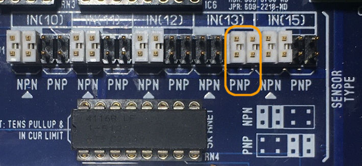
..and move both jumpers to the PNP position:

Then plug the RJ-45 into one of the available input ports on the PIO-100 board, e.g. "IN(10)".
Then on the DOS machine, run ''parallel'' program, (from DOS just run 'parallel', or from within OPCS run '! parallel') and watch the "PIN 10" input change state when the home sensor is interrupted.
Write down the PORT and MASK values for that pin, and put them into the HOMEDEFS.HOM file for the 'homeport' command (at the top of the file) for the channel associated with that sensor.
You can hit ESC or 'q' to exit the parallel program when done.
So if the IN(10) pin is used, and the parallel program shows the PORT/MASK to be 0378/40, and this sensor is for the camera (the "C" channel), then edit the HOMEDEFS.HOM file (using EDIT HOMEDEFS.HOM) and set the 'homeport' command for the C channel as follows:
homeport c 0378 40 40
Then you should be able to use e.g. 'home c' to send the camera to its home position using the sensor to
sense the edge of the slot.
Adjust the slot so that it's in the right position for the camera's film movement, and/or tweak 'start c' section of the HOMEDEFS.HOM file to properly home the channel.
To have the printer software automatically home the 'c' channel, you can add the 'home c' command to the bottom of the OPCSDEFS.OPC file, e.g.
    # Home the camera channel
    ! home c
To home more than one channel in the OPCSDEFS.OPC file, you can specify
multiple channel letters with a space between each, e.g.
    # Home the aerial, main, camera, and fader channels
    ! home a b c d